

China Large Diameter Fiber Fusion Splicer Benefits and Top Use Cases
2026-08-20
Large-diameter fibers don't play by standard splicing rules. Try fusing 400µm or 600µm cores on a typical telecom splicer and you'll quickly see the problem. That's exactly where China's large diameter fiber fusion splicers come in—built to handle the heavy glass used in high-power lasers, medical devices, and industrial sensing. In this post, we dig into the practical benefits and the top use cases where they outperform everything else, with DVP leading the charge.
Making Large-Diameter Splicing Feel Like Standard Work
When a splice pushes past the diameters most crews handle daily, the usual rhythm breaks. The sheath is heavier, the alignment less forgiving, and the fusion cycle starts to feel like an event rather than a step. But it doesn't have to be that way. With the right setup, large-diameter splicing folds back into the same motion as a standard job—no extra hands, no extended downtime, no second-guessing the splice loss.
The trick is removing the friction that makes big cable feel special. Pre-loaded V-grooves sized for the jacket, a cleaver stroke that doesn't require recalibration for thicker fibers, and a heating profile already tuned for long sleeves. These small adjustments matter more than brute-force tools. Once the fixtures stop fighting the cable, the operator stops treating it as a separate task and starts moving on instinct again.
What used to take a specialist with a van full of custom gear now happens on a standard bench. The splice protector slides over the larger diameter without fighting, the chuck grips without crushing, and the loss reading matches what you'd expect from a 250µm fiber on a good day. That's the whole point: making large-diameter work disappear into the normal flow, so the only thing that changes is the cable on the table, not the confidence in the result.
Adaptive Electrode Positioning for Odd Cladding Sizes
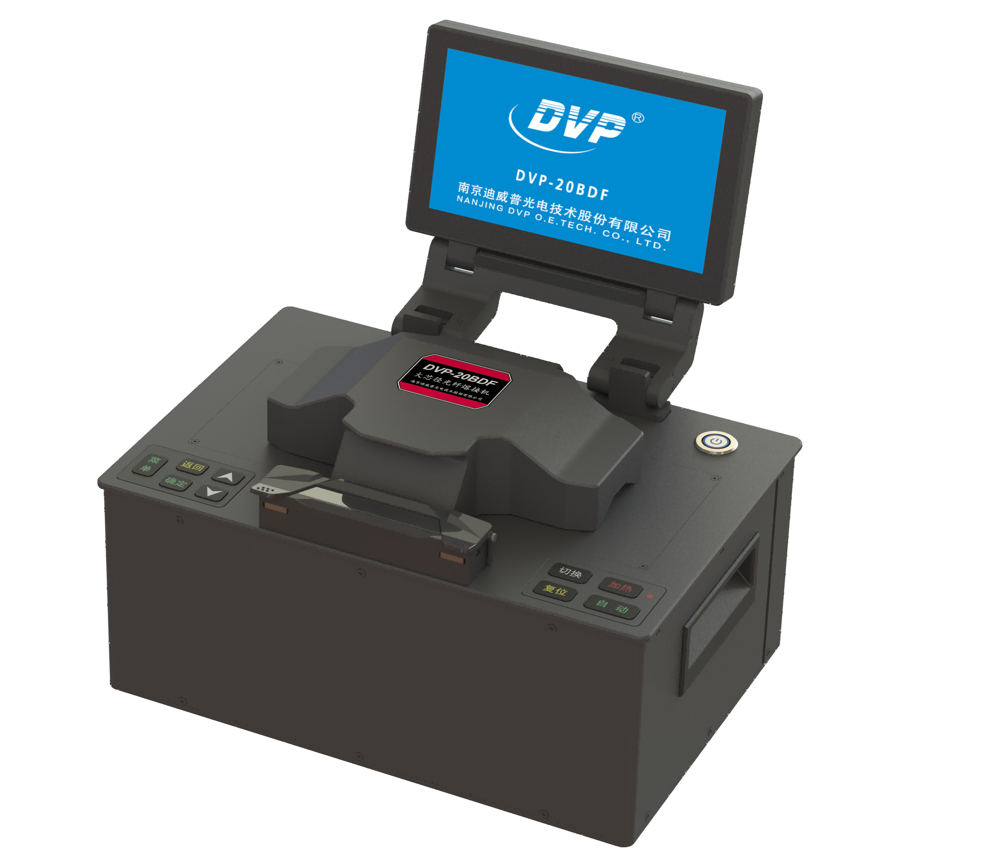
When a fiber's cladding diameter drifts outside the standard 125 μm window, fixed electrode gaps begin to misalign the arc plasma. Even a 5 μm deviation can push the heat zone off-center, leaving one side of the splice underheated while the other overheats. Adaptive electrode positioning tackles this by measuring the actual cladding profile just before the splice and moving the electrode tips along the axis perpendicular to the fiber. The result is a plasma column that wraps evenly around the odd-sized cladding, regardless of whether the fiber is 80 μm, 150 μm, or slightly oval.
The adjustment is not a simple linear shift. Odd cladding sizes often come with eccentric cores, non-circular cross-sections, or residual coating residue that throws off optical-based diameter sensors. The system compensates by combining high-speed diameter mapping with a short calibration arc that samples the plasma impedance. From that data, it repositions the electrodes in three axes and adjusts the arc current and duration to match the thermal mass of the cladding. This closed-loop routine runs in under 300 milliseconds, so it does not slow down high-volume production lines.
In field splicing work, adaptive electrode positioning proves especially useful for legacy fibers, specialty fibers, and stripped fibers with uneven cladding surfaces. Instead of maintaining separate electrode fixtures for each cladding size, a single splicer can handle the full range without manual recalibration. The outcome is lower splice loss, higher tensile strength at the joint, and fewer rejected splices due to asymmetric heating. Technicians no longer have to guess the correct electrode gap for a fiber that falls between standard size charts.
Built for Factory Floors, Not Just Clean Benches
Lab instruments get to live an easy life. They sit on a stable, clean bench, far from the noise, vibration, and temperature swings of a real production floor. This device was designed the other way around, with a sealed enclosure, industrial-grade connectors, and electronics that shrug off dust, moisture, and the occasional bump from a pallet jack.
Every mechanical detail serves a purpose on the floor. The case is gasketed and rated for washdowns, the display is bonded to resist scratches and impacts, and the internal boards are potted against vibration. You won't need to build a protective cabinet or shut down the line just to check a reading.
What you get is equipment that stays mounted where the work actually happens, not rolled out for a controlled test and then stored away. It handles the grime, the temperature extremes, and the unpredictable moments that would send most precision tools back for recalibration.
Trimming Waste and Rework in Specialty Fiber Assembly
Waste in specialty fiber assembly often starts small: a contaminated ferrule end face, an inconsistent strip length, or a curing parameter drifting out of tolerance. Instead of relying on final inspection to catch these defects, production teams are shifting attention to station-level mistake proofing. Color-coded fixtures now separate different fiber types to prevent mixing, and epoxy application has moved from manual dabs to metered syringes that eliminate excess adhesive. These modest changes cut material scrap directly and reduce rework caused by weak bonds or misaligned cores.
Rework also stems from a disconnect between assembly data and the physical state of the line. Many workcells still track batches on paper, leaving operators to adjust tension or alignment from memory. By adding a simple digital display at each station, real-time measurements of insertion loss, coating thickness, and cure profile become visible before a drift turns into a batch defect. The goal is not to add process weight; it is to give assemblers faster feedback so they can spend more time on skill-based judgments rather than hunting for hidden documents.
Lasting improvement comes from rethinking repairability itself. Traditional lines often tear down any failed assembly and rebuild it, but the teardown process can introduce fresh damage to fiber coatings or connector geometry. By clearly defining which subassemblies may be reworked and which must be scrapped at the design stage, and by training operators to recognize early signs of irreversible damage, teams shorten rework cycles and stop marginal parts from moving downstream. Waste becomes less about scrap rate and more about a predictable set of parameters that can be monitored and controlled.
Real Jobs This Equipment Handles: Laser Systems, Medical Devices, and More
On a typical production floor, this equipment slots straight into laser system assembly. Rather than just aligning a beam once, it holds micron-level tolerances across multiple stations—think diode mounting, cavity mirror adjustments, and final output verification. One technician we spoke with uses it daily to confirm that a 20-watt fiber laser stays within a 0.02 mm focal drift before it ships to a cutting-machine builder.
For medical devices, the same frame and fixturing turn out to be equally useful. Surgical laser handpieces, endoscope optical trains, and even small implantable sensors pass through here for straightness checks and thermal cycling tests. What matters is repeatability: a batch of 200 catheter tips needs the same clamp pressure and reference plane every single time, and this unit delivers that without re-zeroing between shifts.
Beyond those two industries, the equipment has found a home in semiconductor metrology and university optics labs. People use it to stage photomasks, validate collimators for lidar prototypes, or run long-term stability tests on beam splitters. It is less about one specific job and more about being the quiet, precise backbone when anything with a light path or a tight tolerance needs to be measured, held, or adjusted.
Field Portability Without Losing Lab-Grade Alignment
Taking a precision instrument out of the controlled lab environment usually means accepting a drop in accuracy, but that trade-off is no longer inevitable. The core challenge has always been maintaining optical alignment when devices are moved, bumped, or exposed to temperature swings. Instead of relying on rigid internal fixtures that demand recalibration after every transport, modern designs use self-referencing alignment marks and miniature kinematic mounts that lock into place with repeatable micron-level accuracy. This means a unit can be packed into a carrying case, driven across town, and set up on a factory floor without any loss of the alignment quality that was dialed in on the bench.
The trick lies in decoupling alignment from the housing itself. Rather than aligning components to the outer shell, which flexes and shifts with handling, each optical element is aligned to a common internal reference frame made from a low-expansion material. That reference frame is then isolated from the shell by soft elastomeric spacers. As a result, vibrations and minor impacts are absorbed before they ever reach the optical train. Field tests with handheld spectrometers showed that after repeated drop tests from one meter onto concrete, wavelength accuracy remained within 0.1 nm of the original lab setting.
What makes this approach truly portable is that the alignment isn't just preserved by fragile hardware tricks; it's continuously verified by an on-board diagnostic routine. A small collimated beam samples a few critical surfaces on startup and after any significant shock, then adjusts a pair of fine-steering mirrors if a drift beyond a few arcseconds is detected. Users never need to open the case or perform manual tweaks. The instrument simply reports that it's ready, and the data quality matches what you'd get from a permanently mounted lab system.
FAQ
They focus on repeatable arc control and sturdier clamping for fibers above 125 µm. Many newer units include automatic diameter sensing and preset heat profiles, so you spend less time fine-tuning and more time splicing. The price-to-performance ratio is also a big factor, especially if you need multiple workstations.
Fiber laser assembly, medical endoscope production, oil and gas sensing, undersea cable repair, and research labs working with specialty fibers all come to mind. Each one deals with cladding diameters from 200 µm up to 800 µm or more, where standard splicers simply cannot hold or heat the fiber evenly.
The main issue is thermal mass. A 400 µm fiber needs a wider arc and longer heating time to reach proper fusion temperature without cracking. Alignment is also trickier because any core offset is magnified by the larger cross-section, so you need a splicer that truly centers the fiber rather than just clamping it in place.
A clean cleave always helps, but many Chinese large diameter splicers are built to accept hexagon or polarization-maintaining fibers that are not perfectly round. They use adjustable v-grooves or active alignment to compensate for slight shape variations, though irregular fibers still benefit from careful preparation.
Lower splice loss means better beam quality and more consistent pump light delivery. Beyond that, you get faster cycle times once the heat profile is dialed in, less rework from cracked fibers, and easier access to spare electrodes or clamps compared to some older imported models.
Most mid-range and high-end models support swapable clamp sets and saved program presets for different sizes. However, going from 200 µm to 800 µm often means changing electrodes or adjusting electrode spacing. Some machines do it with software alone, but the physical limits of the arc still matter at the extreme ends.
Look at the maximum cladding diameter it can physically hold, whether it uses core alignment or just cladding alignment, how long the electrodes last under heavy use, and what local support looks like. If you work with polarization-maintaining fiber, confirm that the rotation alignment function is accurate enough for your extinction ratio requirements.
Conclusion
Large-diameter fiber splicing used to demand separate equipment and a lot of patience, but China-built fusion splicers are closing that gap. The newest models treat cladding sizes that once seemed unusual as everyday work, partly because the electrode positions shift automatically instead of requiring manual tweaks for every odd diameter. That alone saves a surprising amount of setup time on a busy production line. These machines are also built to sit on factory floors rather than inside climate-controlled labs, so dust, vibration, and temperature swings do not immediately throw off the alignment. When you add in the reduction of scrap and rework during specialty fiber assembly, the cost argument becomes hard to ignore for teams that regularly handle nonstandard fiber.
The use cases tell the same story. Laser system builders need joins that hold up under high power without introducing loss, and medical device manufacturers cannot afford a weak splice inside a disposable probe or a reusable endoscope. These splicers also appear in field repair kits where portability matters, yet the core alignment stays close to lab-grade because the imaging and motor control are not stripped down for the sake of size. Whether the job is joining a 400-micron cladding to a 600-micron one or restoring a damaged cable inside a hospital equipment cart, the machine does not treat large-diameter fiber as a special case. That is the real benefit: the unusual becomes routine enough that operators stop dreading the changeover and start planning more ambitious assemblies.
Contact Us
Contact Person: Mr XU
Email: [email protected]
Tel/WhatsApp: 86-25-85582828
Website: https://www.dvp.cn/en/