

Energy-Taking Current Transformer Factory: Key Factors to Evaluate Before Choosing a Supplier
2026-09-18
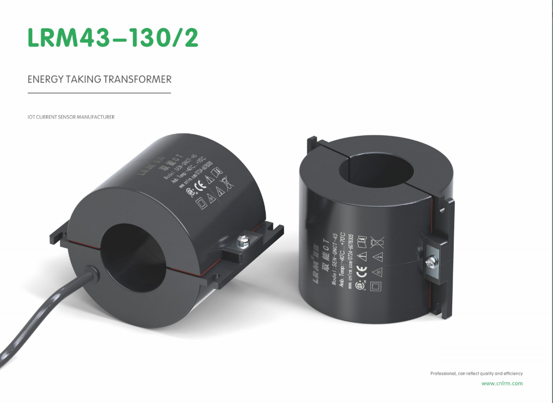
Selecting a factory for energy-taking current transformers isn’t just a procurement checkbox—it’s a decision that quietly determines how your grid monitoring, protection, or metering performs years down the line. While most suppliers quote similar specs, the real differences hide in core material consistency, saturation margins, and thermal behavior under partial load. That’s why we’re examining the practical factors you should pressure-test before signing off. And if you’ve already scanned the market, you’ve likely noticed Xiasen coming up as a reference point worth investigating further.
Core Saturation Behavior at Minimum Pickup Currents
At current levels just above the relay's minimum pickup, many assume the CT operates in its linear region, yet core saturation can still set in early when the burden is high or the secondary loop includes long leads with significant impedance. The first few cycles may show a near-sinusoidal secondary current, but as the core flux creeps upward due to slight DC offset or remanence, the magnetizing branch starts stealing current that should reach the relay. This leaves the measured RMS value below the actual primary quantity, sometimes delaying or entirely preventing pickup for low-magnitude faults.
The behavior differs from deep saturation at high fault currents: here, the waveform distortion is less dramatic, often appearing as a flattened peak or a phase shift rather than a sharply spiked secondary. Even so, protective elements that rely on precise magnitude or angle at minimum pickup, such as sensitive earth-fault or directional overcurrent functions, can see enough error to blur the boundary between operate and restrain. Core material, cross-sectional area, and any residual flux left from a previous interruption all shift the saturation threshold, making the actual minimum pickup current somewhat unpredictable unless the CT is tested under the intended burden.
A practical check is to compare the CT excitation curve against the total burden at the relay tap corresponding to minimum pickup. If the knee-point voltage is only marginally above the required secondary voltage, the core may be entering the early nonlinear region even at low primary currents. Reducing lead resistance, using a lower burden relay input, or specifying a higher class CT usually restores the margin. Field engineers often find that what looks like a relay sensitivity problem is, in fact, core saturation occurring at the low end of the operating range.
What Insulation Aging Means for 20-Year Outdoor Service
Twenty years outdoors is long enough for insulation to face hundreds of thermal cycles, strong UV doses, and occasional moisture ingress. The aging process often begins quietly at the surface, where oxidation slowly eats away the polymer's flexibility while the core remains electrically sound. That mismatch between surface and bulk is what makes routine inspection misleading.
Once the outer skin starts to chalk or crack, water and humidity find an entry point. Microvoids formed by repeated expansion and contraction become pathways for partial discharge, gradually eroding the material from the inside. Field technicians sometimes miss this because the cable or bushing looks structurally fine, yet the dielectric margin has already dropped below the design assumption.
A 20-year service life is less about reaching a fixed expiry date and more about how well the insulation withstands cumulative stress from sunlight, rain, ozone, and mechanical load. The units that survive typically start with enough antioxidant and UV stabilizer headroom to keep the aging curve shallow until seals and enclosures can be replaced or upgraded.
Tracing Magnetic Steel and Resin Lots for Consistent Output
Pinning down exactly which magnetic steel or resin lot went into a batch used to be a puzzle nobody enjoyed solving. You'd end up with coils that looked identical, but behaved differently in the press, and nobody could say why without digging through paper logs. Now the trace starts before material even hits the loading dock. Each steel coil carries a heat number that follows it from the mill through slitting and into lamination stacks. Resin drums get their own lot codes, and both are tied to a production order the moment they are scanned at receiving. That simple act turns a vague “some steel from last month” into a record you can actually pull up in seconds.
The payoff shows up when output drifts. Say your core loss spikes on a Thursday afternoon. Instead of blaming the operator or the oven, you pull the lot history for that run and spot that a new resin batch entered rotation that morning. Maybe the viscosity sat at the edge of spec, or the steel gauge ran thin within tolerance but still shifted the stacking factor. Because the data links material identity to specific press settings and cure curves, you can isolate whether the shift came from the material itself or something downstream. Over time, patterns emerge—certain resin lots behave better with certain steel coatings, and you adjust incoming inspection instead of finding out mid-production.
None of this requires a massive software overhaul. A barcode at the shear, a weigh-station log for resin mixing, and a habit of recording lot numbers against work orders build the backbone. The real challenge is keeping people from bypassing the scan when the line is running late. That discipline is what separates shops that merely track lots from ones that actually use the data to stop variation before it leaves the building.
Custom Designs That Solve Unusual Primary Conductor Challenges
Most off-the-shelf primary conductors assume a straight run, predictable ampacity, and a standard termination. Throw in a switchgear retrofit where the bus bar has to jog around a structural beam, or a substation upgrade squeezed into a footprint laid out decades ago, and that assumption falls apart fast. Custom designs start by mapping the exact geometry, then shaping conductor cross-section, bend radius, and joint placement around what’s actually in the way.
The stranger cases tend to involve more than just space. We have built conductors with asymmetric profiles to balance skin effect under uneven phase spacing, used silver-plated copper laminates to control hot spots at bolted interfaces, and reworked insulation systems for environments where partial discharge and salt fog eat standard materials within a season. Each design gets tested against the same thermal, mechanical, and dielectric stresses it will see in service, not just a generic type test.
What makes these projects work is the back-and-forth with the field crew and the plant engineer. They know which corners are impossible to reach, which connections loosen first, and what previous fixes failed. That input drives the small changes—an angled tap pad, a slightly longer creepage path, a different bolt pattern—that turn a custom conductor from a drawing-board idea into something that installs cleanly and stays reliable long after the startup team leaves.
Accuracy Testing Under Real Burden and Temperature Swings
Accuracy claims mean little unless they hold up when the device is asked to work in conditions that resemble actual field use. Instead of relying on idealized lab references, we run meters and sensors through a matrix of resistive and inductive burdens, each paired with thermal cycles that swing from cold-soak to high-heat operating ranges. The result is a map of drift, phase shift, and linearity errors across the full operating envelope, not just at a single calibration point.
Temperature swings are applied gradually and repeatedly, allowing thermal hysteresis and component stress to surface before they distort real readings. Burden changes are stepped in small increments while voltage and current inputs remain controlled, so any deviation can be attributed to the load characteristic rather than supply noise. This approach catches subtle cross-sensitivity issues: a unit that reads cleanly under a purely resistive burden can show a measurable phase error when inductance rises, and that error often worsens asymmetrically with temperature.
The acceptance threshold is deliberately tighter than the published specification. If a unit drifts by more than a fraction of its accuracy class under combined thermal and burden stress, it is flagged and reworked. That keeps the published accuracy figure honest, because it has already been proven across real burdens and real temperature swings before the datasheet is written.
Field Replacement Logistics and After-Sales Engineering Depth
Field replacement logistics demands more than swapping a failed unit; it requires orchestrating regional depots, forward stocking locations, and technician dispatch in a way that minimizes downtime without inflating carrying costs. A well-tuned after-sales engineering depth means understanding failure patterns at the component level, so the right spare part is positioned before the failure even disrupts the customer's operation. This shifts the conversation from reactive repair to proactive readiness, where field replaceable units are pre-configured, tested, and kitted with the exact firmware and calibration data for the target installation.
The engineering side of this equation focuses on repair-versus-replace decisions, reverse logistics for defective cores, and root cause feedback loops that refine both product design and inventory planning. By embedding diagnostic telemetry into field units, support teams can often identify a failing subassembly remotely, dispatch a replacement part with a single truck roll, and avoid the costly cycle of trial-and-error troubleshooting. This depth of after-sales engineering reduces mean time to repair while also lowering the total number of spare parts kept in the pipeline.
Operationally, strong field replacement logistics relies on clear escalation paths, documented swap procedures, and a closed-loop system where every returned unit is analyzed for wear patterns and failure modes. That intelligence feeds back into both the service parts forecast and the next product generation, creating a continuous improvement loop. When executed well, customers experience faster restorations, field engineers work with greater confidence, and the organization avoids the hidden waste of emergency airfreight and duplicate dispatches.
FAQ
Focus on their ability to handle your order volume without sacrificing lead times. Ask about monthly output, backup production lines, and how they manage peak demand—some factories quote big numbers but crumble under custom specifications.
Request sample cores and ask for material traceability documents. A trustworthy factory will show you batch-level test data for permeability, saturation, and loss, not just a glossy datasheet.
These transformers often run continuously in switchgear or overhead lines. If the epoxy or insulation degrades at high temperatures, accuracy drifts and safety margins shrink. Ask for thermal cycling test reports rather than just rated temperature claims.
Beyond routine ratio and polarity checks, insist on partial discharge testing, insulation resistance under humidity, and accuracy verification at low primary currents—energy-taking CTs must remain linear even when primary current is only a few amps.
Ask them to walk you through a recent customization case. Genuine R&D teams can explain trade-offs in core geometry, winding techniques, and shielding. If every answer sounds like a catalog recitation, that's a red flag.
Yes, because energy-taking CTs are often used for power monitoring and fault indication. Factories with utility project experience understand harsh environmental requirements, long-term reliability, and compliance with standards like IEC 61869.
Look for clear failure analysis procedures, replacement policies, and engineering support for integration. A good supplier won't disappear after delivery—they should help you troubleshoot field issues and provide root cause reports.
Compare cost per unit with warranty terms, failure rate history, and whether they use copper windings versus aluminum. A price far below market usually means compromised insulation or recycled core materials.
Conclusion
Selecting a factory for energy-taking current transformers demands looking beyond catalog specs and into how the units behave at the margins where protection and power harvesting actually happen. Core saturation at minimum pickup currents is often the first thing to unravel in the field; a core that saturates too early can starve a relay or meter just when it needs enough secondary energy to trip or record an event. Insulation aging also deserves serious attention because these devices often sit outdoors for two decades or more, cycling through heat, rain, and UV. Resin systems that look fine in a datasheet may crack or absorb moisture once thermal expansion and partial discharge take hold. A supplier that can trace every magnetic steel and resin lot back to raw material batches gives you a much better chance of consistent output year after year, rather than relying on luck with each shipment.
Custom designs matter most when primary conductors are oversized, oddly shaped, or installed in tight enclosures. You need a factory that asks how the transformer will actually fit around the busbar or cable, not one that insists you adapt to their standard window. Accuracy testing should reflect real burdens and temperature swings, not just a climate-controlled lab bench; if the error shifts when the relay burden changes or the enclosure bakes in summer, that is a genuine problem. Finally, evaluate field replacement logistics and after-sales engineering depth. A responsive factory that keeps drawings, test records, and experienced engineers on hand can walk you through a retrofill or troubleshoot a wiring change without weeks of silence. Together, these factors separate a dependable long-term partner from a vendor that simply ships boxes.
Contact Us
Contact Person: Liu Mengyang
Email: [email protected]
Tel/WhatsApp: 8618727589233
Website: https://www.cnlrm.com/en/