

OEM Rubber Tire Tread Cooling Production Line Efficiency Strategies for Tire Plants
2026-11-16
Ask a tire plant engineer where throughput quietly slips away, and the answer is rarely the extruder. More often, it is the tread cooling line—spray nozzles drifting out of alignment, water temperature creeping up, and line speed capped by guesswork. This post breaks down practical efficiency strategies for OEM rubber tire tread cooling production lines: what to measure first, where small adjustments recover the most capacity, and how to avoid the retrofit traps that keep repeating. The team at AUGU AUTOMATION has walked enough OEM tread cooling lines to keep this guide focused on changes that pay back without a major rebuild.
Where Tread Cooling Actually Slows Down in an OEM Tire Plant
In a lot of OEM tire plants, the actual slowdown tied to tread cooling doesn't happen in the water tank or the spray tunnel. It happens just after, when the tread is still warm but the surface temperature has already dropped. That's where the line speed gets pulled back to let the cross-section settle. Quench too hard and the outer skin contracts faster than the core, so treads come out of the bath looking fine but carry enough internal stress to change cut lengths once they reach ambient temperature. The fix is rarely more cooling capacity; it's usually a longer low-tension conditioning run at moderate temperature, which costs more line time than the heat removal itself.
The second place where cooling logic falls apart is right before winding. Even if the tread is cool enough, residual water in the grooves or sipes will ruin a roll. High-volume air knives can strip surface water, but they miss the film that sits in sharp corners of the pattern. Operators end up dropping line speed and adjusting air knife angles batch to batch, especially after a die change. That trial-and-error period can take longer than the actual cooling cycle, and it never shows up in the standard cycle-time estimate because it gets logged as setup rather than cooling.
There's also a process limit that appears when certain high-styrene or heavily filled tread compounds are involved. On those recipes, aggressive cooling creates a harder outer layer that doesn't bond well later, so the specification forces a slower cooling ramp through a buffer zone. This isn't a bottleneck you can engineer away with bigger chillers or colder water. It's a residence time requirement, and the area usually gets a storage loop or accumulator so downstream stations don't starve. Even with that buffer, the tread still needs the extra dwell time, and that's where the real pace is set.
Rethinking Spray and Airflow Settings Instead of Adding More Chillers
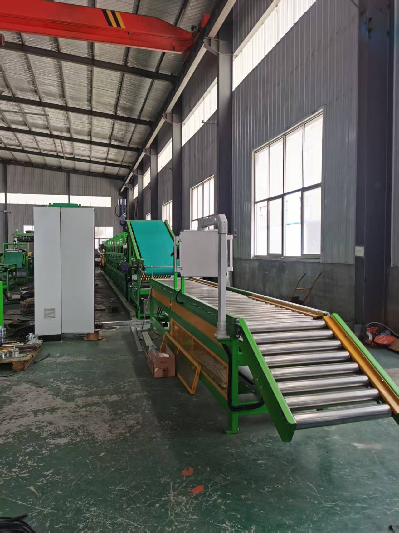
Most plants reach for another chiller the moment leaving-water temperatures climb, but that instinct often ignores how much capacity is already being lost at the spray nozzles and fan inlet. Uneven water distribution leaves sections of the fill nearly dry while other areas flood, and the resulting channeling cuts heat rejection far more than a slightly undersized chiller does. Checking nozzle pressure, spray patterns, and drift eliminators is cheaper than pouring a new pad.
Airflow deserves the same scrutiny. Inlet obstructions, loose fan shrouds, and badly angled blades create recirculation that pulls warm discharge air straight back into the intake. That single issue can raise the effective wet-bulb temperature enough to wipe out several degrees of approach. Sometimes reducing fan speed or adjusting blade pitch actually improves contact time and lowers water temperature because the air no longer short-circuits through the path of least resistance.
Small changes in spray density and air balance routinely deliver two to four degrees of improvement at the condenser water return, which is often the difference between deciding against a chiller addition and approving one. Once the tower or evaporative condenser is tuned, the existing chillers stop fighting a bad heat-rejection loop and capacity that looked missing tends to reappear.
How Uneven Cooling Creates Hidden Waste at the Splice Station
At a splice station, the joint rarely fails all at once. More often, one side of the bonded area cools faster than the other because nearby rolls, ambient air movement, or contact with metal parts pulls heat away unevenly. That temperature difference creates a small but persistent stress gradient across the splice. The material may look acceptable when it leaves the station, but the real issue appears further down the line as edge curl, micro-wrinkles, or a slight change in web tension.
Uneven cooling also changes how tapes and adhesives set. If the center of the splice holds heat while the edges stiffen, the adhesive layer can cure into a non-uniform thickness. On coated films or laminates, this shows up later as gauge bands or soft spots that are hard to trace back to the splice. Operators often respond by increasing waste allowances or slowing the line, which hides the true cost instead of fixing the thermal imbalance.
The hidden waste is rarely counted as splice loss. It appears in rejected rolls, extra slitting, or repeated checks at quality control. A splice that cools unevenly can also trigger downstream breaks that get blamed on tension control. Simply shielding the area from drafts, pre-warming the splice tooling, or allowing a short controlled cool-down before pulling the web can remove much of that variation before it becomes waste.
A Practical Retrofit Path for Older Cooling Lines Running Near Capacity
Most older cooling networks that look maxed out are actually losing usable capacity to flow restrictions, fouled exchangers, and control settings that have drifted over time. Before adding new equipment, it pays to walk the headers and measure what is really happening: pressure drop across strainers, supply-to-return temperature splits at each branch, and pump operating points against their curves. In many plants, a closed isolation valve or a worn balancing valve is quietly stealing enough flow to mimic a capacity shortfall.
Once the as-built hydraulics are understood, the first retrofit dollars tend to go further in restoring lost performance than in expanding the plant. Cleaning chiller bundles and cooling tower fill, replacing corroded strainer screens, trimming impellers that no longer match the system curve, and switching fixed-speed pumps to variable-speed control can uncover headroom that avoids larger capital work. It also helps to retune supply water setpoints and staging logic because some lines show false overload simply because multiple chillers are running against each other.
Where demand still sits close to the limit after these corrections, a phased retrofit makes more sense than a single large replacement. Upsize only the most restrictive headers first, add a small supplemental heat rejection skid tied to the existing controls, or move a handful of high-load processes onto a dedicated loop so the main headers stop swinging with production spikes. Leaving clean isolation points and temporary bypass connections in place lets the plant switch over piece by piece without a long shutdown.
Setting Line Speed and Spacing Around Tread Stability, Not Guesswork
When a line runs slightly faster than the tread can settle, the defects rarely announce themselves right away. They show up later as edge lifting, uneven gauge, or a wandering centerline. The practical approach is to let tread stability set the ceiling for speed, then adjust spacing to keep each section from fighting the one ahead of it.
The plants that get this right usually start with a narrow window. They do not push the whole line to a target number and hope the material behaves. Instead, they watch the tread through the first few meters after extrusion, note where it begins to shimmy or twist, and back the speed down until that movement disappears. Only then do they set the spacing between lengths so the next piece never crowds the one still cooling.
That shift from guesswork changes how operators talk about problems. Rather than asking how fast the line can run, they ask how stable the tread is at a given speed, and what spacing keeps that stability intact through the transfer points. It sounds slower, but the reduction in scrap and restart time usually more than makes up for it.
Signs Your Cooling Zone Is Drifting From Spec During a Shift
A cooling loop that starts wandering rarely announces itself with a single obvious failure. More often, the clues stack up quietly: the water return line feels warmer than it did an hour ago, a thermocouple shows a few degrees of drift on one cavity, or the flow indicator sits just below the mark you noted at startup. Those small shifts tend to show up in the parts before they show up on a gauge.
Watch for dimensional changes that don't trace back to material or pressure adjustments. A cavity that suddenly runs hotter will produce sink marks, warped bosses, or gloss variations in the same location cycle after cycle. If the operator begins compensating with longer hold times or tweaking barrel temperatures just to keep parts in tolerance, that's often a sign the cooling side has moved off its original balance.
Another quiet indicator is a cycle time that creeps upward without a change in the recipe. When heat removal slows, the mold holds temperature longer, and the controller waits for the setpoint before allowing the next shot. A drop in flow from a partially clogged channel or a failing solenoid can mimic a worn barrel, but checking the water manifold first will usually save a lot of unnecessary adjustments.
FAQ
Uneven water distribution and poor air flow usually slow things down before the extruder does. A lot of plants run the line faster but still get warm spots because the spray bars are partially clogged or the nozzles are pointed at the wrong angle. Rechecking nozzle alignment and replacing worn pump seals often recovers more capacity than a full line rebuild.
If the water is too cold, the tread surface can set while the core is still warm, which leads to unpredictable shrinkage later. If it is too warm, the line has to run slower to hit the target temperature at the exit. Keeping the supply within a narrow band, usually a few degrees around the plant's setpoint, gives the most repeatable dimensions.
Closed-loop systems keep water chemistry consistent and reduce the amount of fresh water that has to be treated. They also prevent seasonal temperature swings from changing cooling behavior. The trade-off is the need for a properly sized chiller or cooling tower and regular filtration.
The best results usually come from matching line speed to the compound's heat history rather than pushing for the highest throughput. Running slightly below the maximum speed but with better spray coverage can actually increase daily output because there are fewer rejected treads and fewer stops to clear jams.
The first step is to stage pump speeds to actual demand instead of running every pump at full output during slow production periods. Air knives can also be positioned to remove excess water before final drying, which lowers dryer energy. Small adjustments here usually pay back quickly because cooling and drying run continuously.
Tread profiles are not flat, so the thick shoulder areas need more direct cooling than the thin edges. If nozzles are not aligned to the profile, operators often compensate by increasing water flow, but that only floods the line and makes drying harder. Proper placement targets the heat load where it actually sits.
Weekly inspections of spray nozzles, strainers, belt tracking, and pump vibration catch most failures before they stop production. Plants that log water pressure and temperature trends also spot slow degradation early. Replacing a worn nozzle or cleaning a strainer on a scheduled stop is far cheaper than a mid-shift breakdown.
Conclusion
Most throughput losses in an OEM tread cooling line show up well before the chiller plant reaches its limit. The real restrictions tend to sit in spray nozzle coverage, uneven airflow across the belt, and splice-station rework that nobody tracks until scrap numbers climb. When tread edges cool faster than the center, the material can handle differently at cutting and splicing, so operators slow the line or add buffer spacing to compensate. That response feels safe but quietly reduces daily output. Instead of installing additional chillers, plants often get more immediate gains by resetting nozzle angles, balancing air distribution, and fixing water carryover that makes cooling look adequate on the exit pyrometer while leaving internal heat in the tread that later shows up as dimensional variation at the splice station.
Older lines running near capacity can usually be brought closer to spec with a targeted retrofit that includes upgraded spray bars, better drainage, and variable-speed fans tied to actual tread temperature rather than fixed settings. Line speed and spacing should be derived from tread stability after cooling, not from a standard recipe, because compound changes and ambient shifts move the stable operating window during a shift. Warning signs include rising surface temperature drift, water pooling on the belt, higher splice scrap, and operators repeatedly trimming speed in the same zone during the same shift. Monitoring those indicators at shift level, ideally with a short temperature log and visual check, makes the cooling process manageable instead of reactive.
Contact Us
Contact Person: Lareina
Email: [email protected]
Tel/WhatsApp: +86 17561696737
Website: https://www.auguauto.com/