

Rotary Union Factory: Inside the Precision Manufacturing Behind Leak-Free Fluid Transfer
2026-09-30
Behind every leak-free fluid transfer system lies a story of precision you rarely see. At MOFLON, rotary union manufacturing isn't just machining—it's a controlled blend of metallurgy, micron-level tolerances, and obsessive testing. This is where hidden leaks are designed out before they ever have a chance to fail in the field.
Turning Raw Bar Stock into Balanced Rotors
The path from a solid steel bar to a precisely balanced rotor starts with careful material selection. Not all bar stock behaves the same under machining stress or high-speed rotation, so shops often choose alloys with consistent grain structure and predictable thermal expansion. Once the blank is cut, the real work begins: rough turning removes the bulk of material while leaving enough stock for finish passes. But here's the part many people overlook—balance isn't something you simply add at the end. It starts with how evenly the bar is centered in the chuck and how symmetric your initial cuts are.
After roughing, a stress-relief cycle can be a game changer. Bar stock carries internal stresses from rolling or drawing, and those stresses release unevenly as metal is removed. If you skip straight to finishing, the rotor might measure fine on the bench but shift a few tenths after it spins up to operating speed. Instead, letting the roughed part normalize—sometimes with a low-temperature soak—keeps later distortion to a minimum. Then finish turning can hold tighter concentricity between bearing journals and the rotor body, which directly affects how little correction weight you'll need during balancing.
At the balancing stage, the goal is to remove material from the heavy side rather than bolting on counterweights. A good machinist will leave a small amount of stock in designated areas, such as the rotor face or the outer diameter, specifically for this purpose. By drilling or milling shallow pockets based on the balancer's readout, you shift the mass distribution without weakening the part. The result isn't just a rotor that passes a vibration spec on paper—it's one that stays smooth across a range of speeds, because the underlying geometry was built symmetric from the very first turning pass.
The Tolerance Hunt Behind Drip-Free Seals
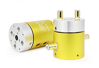
Achieving a genuinely drip-free seal often comes down to chasing tolerances that feel almost absurd on paper. A few microns of deviation in the mating surfaces can turn a supposedly leak-proof design into a slow, persistent weep. Engineers spend weeks narrowing the gap between the ideal CAD model and what actually comes off the tooling, because the boundary between dry and damp isn't a bold line—it's a shadowy zone where the smallest manufacturing drift quietly defeats the spec sheet.
That hunt grows harder when temperature swings and pressure pulses enter the picture. A seal that holds perfectly on the bench at room temperature may open a microchannel once the assembly warms up and the materials relax into their real-world shapes. The tolerance stack isn't just about dimensions; it's about how those dimensions shift under load, how surface roughness traps or releases fluid, and how the elastomer's compression set evolves after a few thousand cycles. Every variable adds another thread to a tolerance web that can take months to untangle.
What separates a reliable seal from a near-miss isn't usually a breakthrough material or a clever geometry. It's the willingness to measure the unglamorous details—burrs, waviness, eccentricity, the exact durometer after post-cure—and then push suppliers harder than feels reasonable. Drip-free performance is rarely a single design decision. It's the residue of hundreds of small compromises, each one argued over until the leak path simply has nowhere left to go.
Sealing Faces That Stay Dry Under Pressure
A well-matched pair of sealing faces doesn't simply press together; it actively sheds fluid as load increases. The trick lies in balancing contact pressure across the entire ring—too little invites weeping, too much accelerates wear and heat checking.
Modern hard-face combinations like reaction-bonded silicon carbide against carbon-graphite create a near-polished interface that resists pitting and edge chipping. When combined with a slight hydrodynamic waviness, the faces ride on a micro-film at speed yet snap tight during low rotation or standstill, keeping the dry side genuinely dry.
Installation and alignment remain the final safeguard. A face that is lapped flat to within two helium light bands will still leak if bolting torque pulls the housing out of round. Precision assembly, clean lubrication, and controlled axial movement let the sealing faces stay dry long after startup pressure spikes fade.
Assembly Steps Where One Flaw Invites Leaks
When piecing together the housing, pay close attention to the gasket channel. A tiny nick or a slightly uneven torque pattern on the bolts can open a path for fluid to escape almost immediately. Many rebuilds fail here not because the parts are wrong, but because the sequence gets rushed.
Start with clean, dry mating surfaces and follow the recommended tightening order in at least two passes. If the manual calls for a specific sealant, apply it thinly and evenly; too much can squeeze into the flow path and cause just as much trouble as too little. Recheck the fasteners after the first warm-up cycle. The goal is not just to stop a visible drip, but to prevent the slow seep that shows up days later and ruins an otherwise careful job.
The Test Bench Every Rotary Union Must Survive
A proper test bench for rotary unions does more than spin a fitting and check for drips. It replicates the exact torque loads, pressure spikes, and temperature swings the component will encounter on a printing press, wind turbine, or machining center. The setup typically includes a variable-speed drive motor, a closed-loop fluid conditioning unit, and instrumentation to track inlet and outlet pressure, flow rate, and case temperature in real time.
One of the first things the bench measures is seal integrity under cyclic pressure. A rotary union may run for hours at a steady 10 bar, only to fail when the system suddenly drops to 2 bar and rebounds. Test programs therefore alternate between high and low pressure plateaus while the shaft rotates at full speed. Leak sensors positioned around the seal cavity and bearing housing log even small weepage events, while torque transducers catch the early friction increase that often precedes scoring or polymer seal breakdown.
Beyond pressure cycling, endurance runs are designed to compress years of service into a few weeks. The union must survive continuous duty at maximum rated temperature and speed without exceeding a specified leak rate or developing excessive rotational drag. Data from these runs is reviewed against pass/fail thresholds that account for media type, seal material, and expected maintenance intervals. Only after a unit clears thermal shock, vibration, and dry-run segments is it approved for field trials.
Material Pairings Built for Years of Fluid Cycles
Some material combinations only survive a few hundred cycles before micro-cracks start weeping. The pairings we rely on are chosen the way a mechanic picks an O-ring for brake fluid: not by datasheet alone, but by watching what happens after repeated temperature swings and pressure spikes. PTFE against hardened stainless, EPDM against glycol, Viton against hot oil—these aren't arbitrary matches. Each one has a history of surviving the slow fatigue that kills cheaper setups.
What matters most is how the two materials argue with each other. A slightly softer seat against a polished metal ball will wear into a better seal over time, while a mismatched elastomer will swell or turn brittle after a few thousand cycles. We keep our pairings under load in test loops longer than most products stay on a shelf, because fluid cycling isn't a single event—it's millions of tiny movements that expose any weakness in the original match.
When you find a pairing that still holds pressure after years of thermal expansion and contraction, you don't change it. You document it, replicate it, and make sure every replacement part carries the same material spec. That's the only way a fluid system earns the right to be called maintenance-free.
FAQ
It lets pressurized liquid or gas move between a stationary pipe and a rotating component—like a drum, spindle, or indexing table—without twisting the supply lines. The core challenge is maintaining a seal while everything spins at speed.
They pair tight machining tolerances with surface finishing techniques that create a near-mirror seal face. Every unit then goes through a pressure decay test and a rotational leak check before it leaves the floor, so defects get caught early.
It's huge. Stainless steel housings resist corrosion, while seal materials like PTFE, ceramic, or silicon carbide are chosen based on the fluid type, temperature, and speed. Matching the material pair to the application is often what separates a long-life union from one that fails in months.
A few microns of runout on the rotor or a slightly off-center bearing seat will cause uneven seal wear and early leakage. The factory uses CNC grinding and in-process measurement to hold tolerances that keep the rotating assembly concentric under load.
One standard test is to clamp the union into a test rig, rotate it at rated speed while pumping fluid at 1.5 times the working pressure, and monitor for any pressure drop or moisture around the seals. Some lines also run a dry-run cycle to check seal break-in behavior.
You'll find them in paper mills, steel continuous casting, injection molding, wind turbines, and even food processing. Anywhere a rotating roll or drum needs heating, cooling, or hydraulic power without a tangle of hoses.
Even the best-built union needs clean fluid and proper alignment. Filtering out particles above 10 microns and checking radial loads on the rotor can double or triple the service interval. Most failures we see come from contamination or side loads, not manufacturing defects.
It's the combination of in-house seal design, controlled assembly environments, and test cells that replicate real operating conditions. A generic shop can machine parts, but they often miss the subtle details like seal gland geometry and spring preload that make leak-free operation reliable.
Conclusion
Turning raw bar stock into balanced rotors is only the starting point inside a rotary union factory. Every rotor begins as a solid piece of metal, machined down to tolerances measured in microns. The hunt for drip-free seals means chasing imperfections that are invisible to the naked eye—slight deviations in flatness or concentricity that would let fluid escape. Sealing faces are lapped and polished until they stay dry under full operating pressure, a process that rejects more parts than it passes. Without this fanatical attention to surface finish and balance, the rotating union would vibrate, wear unevenly, and leak within hours. The tolerance hunt extends beyond the rotor itself: every mating surface, every groove for an O-ring, every spring pocket is checked against a master gauge, because even a two-micron error can turn a seal into a slow drip.
Assembly is where one flawed step invites leaks, so each component is cleaned, inspected, and fitted in a controlled environment. Technicians follow torque sequences and alignment checks that leave no room for guesswork. The finished rotary union then faces a test bench that simulates years of fluid cycles—pressurizing, rotating, and temperature-cycling the seal until it either proves itself or fails catastrophically. Material pairings matter just as much as machining: carbon graphite against hardened steel, silicon carbide against tungsten carbide, each combination chosen for specific fluids and pressures. Those pairings are not static; they are run through accelerated wear tests that compress a decade of service into a few weeks, revealing whether a seal face will glaze, pit, or hold its polish. The result is a rotary union built not just to pass inspection, but to survive thousands of hours of continuous duty without a single drop lost.
Contact Us
Contact Person: Xiangpin Li
Email: [email protected]
Tel/WhatsApp: 86 186 1706 8578
Website: https://www.moflon.com