

Top Stamping Parts That Drive Precision in Metal Fabrication
2026-11-16
Precision in metal fabrication often comes down to a handful of unsung components. From blanking dies to deep-drawn enclosures and progressive tooling inserts, the right stamping parts quietly determine whether a sheet becomes a flawless bracket or a costly reject. In this post, we break down the top stamping parts that drive repeatable accuracy, faster cycle times, and cleaner edges on the shop floor. Whether you are troubleshooting tolerance drift or planning a high-volume run, understanding these pieces can change how you specify tooling. At BOYIKUN, we have seen how small design choices in these parts separate stable production from constant adjustment. Read on to see which components deserve a closer look before your next build.
Fineblanked Gears That Make Secondary Machining Optional
Conventional stamping leaves a fractured, torn band along the tooth profile. Fineblanking replaces that with a fully sheared edge that comes out of the die nearly polished. For many gear designs, tooth form, surface finish, and flatness arrive close enough to final condition that hobbing, shaving, and grinding fall off the routing altogether.
The advantage is not simply fewer operations. It is the difference between a part that must be located, clamped, and re-cut across several setups and a part that moves from press to deburring to assembly. Once the blanked surface becomes the working surface, tolerance stacks shrink, perishable tooling costs drop, and lead time stops depending on the slowest finishing cell.
Fineblanking does not erase every secondary step. Some bores, face details, or hardened surfaces still justify a light follow-up pass. What changes is the starting point. Manufacturers begin to treat the press as the defining operation rather than rough stock waiting to be corrected.
Deep Drawn Housings With Uniform Walls in Tight Radii
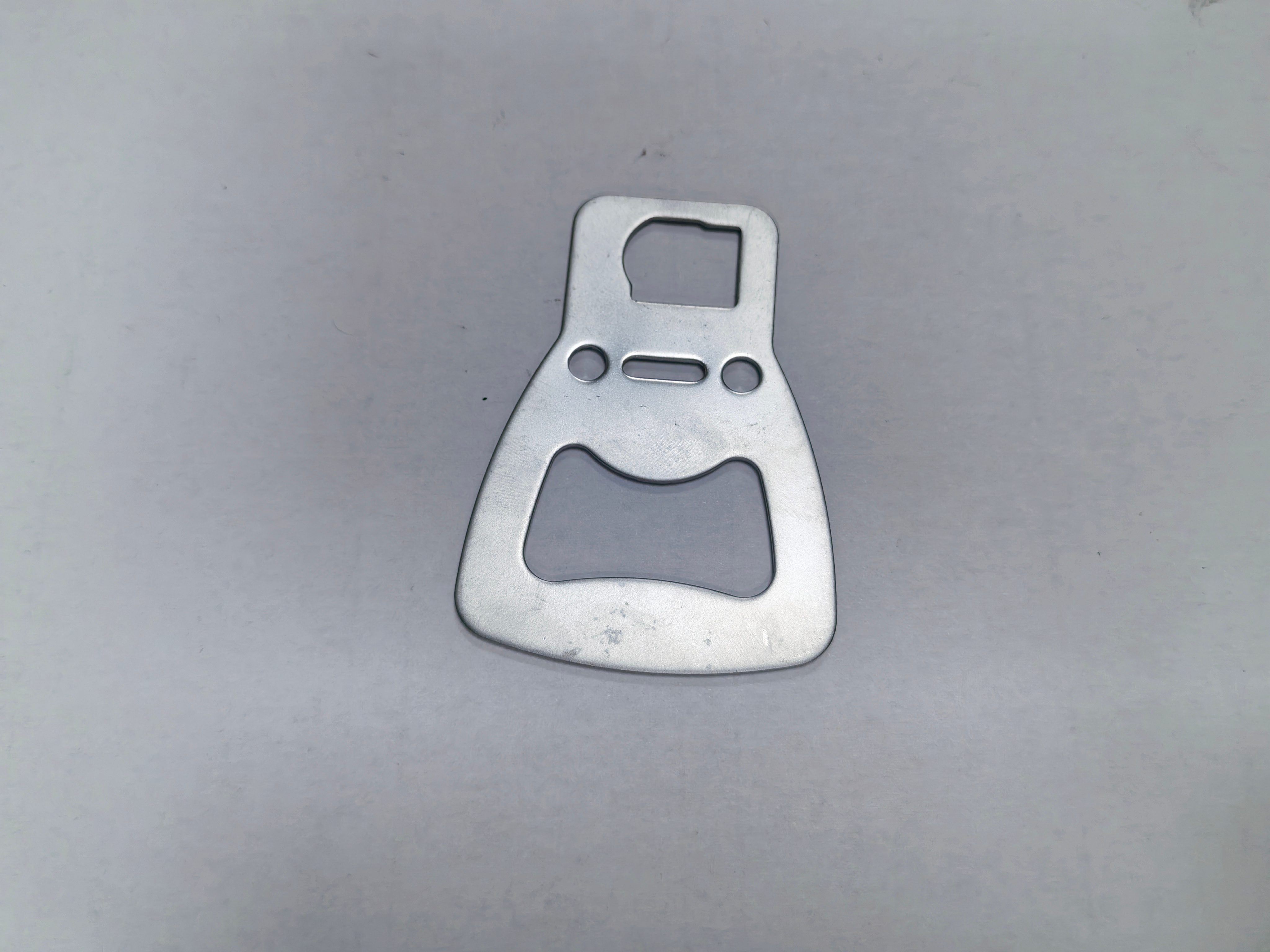
Achieving uniform walls in deep drawn housings gets considerably more difficult once corner radii tighten. The blank does not flow into the die at the same rate everywhere; shorter material paths near a tight radius tend to thin first, while straight sections pull metal inward and leave thickened bands. Tooling has to be tuned around that imbalance rather than fighting it, often through staged draw reductions, carefully adjusted blank holder pressure zones, and slightly oversized initial radii that are ironed into final geometry in later stations.
When radii approach the material thickness or less, forming pressure concentrates sharply. This is where small changes in punch nose geometry, lubrication type, and even grain direction in the strip begin to show up as splits or local necking. A practical approach is to design the first draw with more generous geometry than the finished print and bring the corner in progressively. That sequence keeps the wall cross-section more consistent because the metal has already been work-hardened and redistributed before it is forced into the tightest features.
For housings that must maintain a precise internal envelope, uniform wall thickness in tight radii is not simply a cosmetic target. It affects how mating components seat, how the part handles load around bend lines, and whether plating or coating builds evenly. Tooling houses often rely on simulation runs and sectioned prototypes to verify material distribution, then adjust draw beads and punch timing until the thinnest section remains well inside tolerance. The result is a housing that looks straightforward but carries the fingerprints of deliberate, station-by-station refinement.
Micro-Terminal Strips for Dense Board-to-Wire Interfaces
As board real estate keeps shrinking, the pressure on interconnects has moved from simply fitting to staying reliable under thermal cycling, vibration, and rework. Micro-terminal strips address that by trimming the housing footprint and tightening contact spacing without pushing signal integrity into the danger zone. The better designs rely on staggered tails and thin-wall insulators rather than just smaller screws.
Assembly is where these parts earn their keep. A dense board-to-wire interface usually means a row of signals packed next to power returns, with very little forgiveness for misplaced strands or cold joints. Micro-terminal strips let line operators use consistent crimp or press-fit tooling, so the termination quality stops depending on who happens to be holding the soldering iron that day.
It also helps to look past pin count. Alloy selection, polarization, and the way the solder tails land on the pad pattern can determine whether a connector survives repeated service cycles. For mixed power and signal edges, strips with a few dedicated high-current positions often eliminate an extra header and free up space for routing, test points, or shielding.
Progressive Die Brackets That Set Assembly Alignment Early
In a progressive die, brackets do more than hold tooling in place—they establish the relationship between the upper and lower halves before the cutting details are fully seated. Setting that alignment early means locating the bracket faces against the same datums used for the guide pins, then checking daylight and shut height while the die is still partially open. It sounds like a small step, but many builds drift because brackets are fitted after the working components, forcing the alignment to adapt instead of leading it.
A practical way to keep that early reference intact is to mill the bracket seats in the die shoe and punch holder in one setup, then use temporary dowels that match the final pin diameters. Once a strip is pulled through and the carrier shows no sign of side pull, the brackets can be doweled and screwed while the die is still on locators. That keeps the initial alignment from becoming a loose suggestion rather than a fixed reference for everything that follows.
The benefit shows up later when sections are sharpened or replaced. Because the alignment was locked in with the brackets before the cutting stations were firmly seated, reassembly does not require nudging each station back into position. The die returns to the same closing path it had originally, which reduces edge contact and keeps pilot release timing more predictable over the life of the tool.
Stainless Spring Clips Built for Constant Load Cycling
Constant load cycling puts ordinary spring clips through brutal punishment—tiny deformations accumulate until the metal loses its grip. These stainless clips are engineered specifically to shrug off that fatigue. The material choice isn't incidental; stainless steel's high yield strength and resistance to work hardening allow each flex to recover fully, cycle after cycle, without developing the micro-cracks that typically spell early failure.
What sets them apart is the geometry. The spring loop is drawn with a slightly elongated throat, distributing stress across a broader curvature rather than concentrating it at a single bend point. That means when the clip is opened and closed thousands of times—on access panels, battery compartments, or quick-release covers—the force required stays consistent. You won't find the clip suddenly going soft or snapping at the apex.
In practice, that reliability shows up as fewer warranty returns and less downtime on equipment that has to be opened regularly. Whether it's a marine inspection hatch or an industrial enclosure, a stainless clip that holds its tension over tens of thousands of cycles isn't just a component—it's one less variable to worry about in the field.
Laminated Busbar Stampings for Cooler Power Distribution
Laminated busbar stampings change how high-current paths are routed inside cooler power distribution modules. Instead of relying on thick copper bars or bundled cable runs, the stamped layers are stacked with thin insulation between them, which keeps inductance low and simplifies the physical layout around cooling channels and fans.
The stamping process itself allows for tight tolerances and repeatable bend profiles, so each busbar drops into place without forcing alignment or adding stress to terminations. In cooler applications this matters because space around heat sinks and airflow paths is limited, and a well-formed laminated assembly can follow those contours while still carrying the required current with less temperature rise at connection points.
Most designs use copper or copper alloy stock, with tin or silver plating where connections are made. Edge burrs and flatness are controlled during stamping because small defects can lead to uneven pressure across the lamination stack or localized heating. When the layers are compressed and terminated properly, the result is a compact current path that supports cleaner wire routing and easier service access inside the enclosure.
FAQ
Thin-gauge connectors and lead frames tend to carry the tightest expectations because their pitch spacing and mating surfaces leave little room for drift. A good progressive die with in-die measurement holds those features repeatably without constant sorting.
A stamped copper or aluminum busbar removes several connection points and gives the current a cleaner path. Edge radii, flatness, and hole positioning all stay more repeatable than a hand-built harness, so contact resistance and heat rise stay predictable.
Deep drawing forms a seamless shell with relatively uniform wall thickness and no weld distortion. Mounting bosses and lid seats stay where they should be without straightening or secondary machining, which removes stack-up variation during assembly.
They absorb variation from mating components while keeping a steady normal force. The material temper, bend radius, and grain direction all have to work together, otherwise contact force fades after repeated cycles and intermittent faults appear.
Brackets often define the location of an entire subsystem, so their hole-to-edge and hole-to-hole relationships matter more than they look. If the datum alignment is loose, every component mounted to that bracket inherits the same misalignment.
Base flatness, fin spacing, and material thickness control the thermal interface. A slight bow or uneven fin pitch reduces clamping pressure against the component, creating hot spots that are hard to catch until thermal testing fails.
Ask for capability data on geometries similar to the part, not just a generic tolerance chart. First-article measurements showing Cpk on critical features matter, along with how the supplier controls burr direction, springback, and tool maintenance intervals.
Placing tight tolerances on every feature usually hurts more than it helps. It raises cost and forces unnecessary secondary work. A stronger approach is to tolerance only the functional datums and allow non-critical areas to move within a reasonable process window.
Conclusion
Precision stamping has quietly become the stage where many downstream manufacturing problems are solved before they ever reach assembly. Fineblanked gears make the case directly: their edge condition and dimensional stability are clean enough that secondary machining turns into an option instead of a fixed cost. Deep drawn housings follow the same logic by holding wall thickness uniform through tight radii, which keeps mating parts predictable and reduces the sort of correction work that erodes margin. The value is not only in hitting a tolerance; it is in removing steps that used to be assumed necessary.
At the miniature end, micro-terminal strips have to hold pitch and flatness within ranges that leave no room for drift in dense board-to-wire interfaces. Progressive die brackets take that idea into assembly by setting alignment early, so variation never gets a chance to compound. Stainless spring clips then carry precision into repeated service, handling constant load cycling without losing grip or showing permanent deformation. Laminated busbar stampings manage electrical and thermal demands together, enabling cooler power delivery in tighter spaces. Across these examples, stamping becomes less about blanking metal and more about embedding performance, alignment, and reliability into the part before it leaves the die.
Contact Us
Contact Person: Xianchen Hu
Email: [email protected]
Tel/WhatsApp: 86-13248645200
Website: https://www.hexnb.com/